-
Ref.: YD-ESP32-S3 N16R8
-
The device uses the ESP32-S3 chip, which can be used for the test prototype of the Internet of Things application and can also be used for practical applications. It is equipped with two USBs, one is a hardware USB-to-serial port (CH343P WCH Qinheng), and the other is ESP32-S3 usb port.
-
- [CircuitPython 8.2.8] Built-in modules available: _asyncio, _bleio, _pixelmap, adafruit_bus_device, adafruit_pixelbuf, aesio, alarm, analogbufio, analogio, array, atexit, audiobusio, audiocore, audiomixer, binascii, bitbangio, bitmaptools, board, builtins, builtins.pow3, busio, busio.SPI, busio.UART, canio, collections, countio, digitalio, displayio, dualbank, errno, espcamera, espidf, espnow, espulp, fontio, framebufferio, frequencyio, getpass, gifio, hashlib, i2ctarget, io, ipaddress, json, keypad, keypad.KeyMatrix, keypad.Keys, keypad.ShiftRegisterKeys, math, mdns, memorymap, microcontroller, msgpack, neopixel_write, nvm, onewireio, os, os.getenv, ps2io, pulseio, pwmio, qrio, rainbowio, random, re, rgbmatrix, rotaryio, rtc, sdcardio, select, sharpdisplay, socketpool, ssl, storage, struct, supervisor, synthio, sys, terminalio, time, touchio, traceback, ulab, usb_cdc, usb_hid, usb_midi, vectorio, watchdog, wifi, zlib; Included frozen(?) modules: neopixel
Pinout:
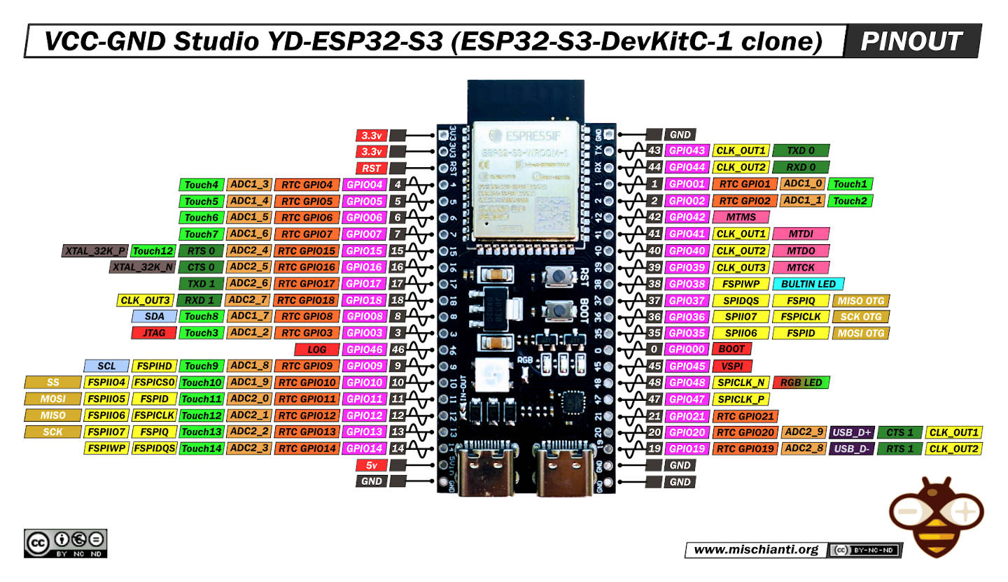
-
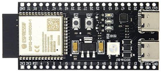
The ‘ESP32 S3 DevKitC1 Clone’ board has a jumper called 'RGB', another called 'IN-OUT', and another called 'USB-OTG', all open. But it may be necessary to solder the jumper for the devices to work.
-
- The 'IN-OUT' jumper, when closed, bypasses one diode, making USB VBus power coming to 5Vin. If 5Vin is also connected to external source, it can get back-fed by USB, which is usually undesirable. But USB bus is protected by another diode, it cannot get back-fed by external source. When In-Out is open, 5Vin and USB VBus are separated by diode, USB power does not come to 5Vin.
-
- The 'USB-OTG' jumper, when closed, connects together USB VBus lines from both USB-C connectors.
-
The RGB LED did not work with common digitalWrite() commands. RGB LED only worked with neopixelWrite() commands.
-
- Arduino IDE: There is a BlinkRGB under the ESP32->GPIO examples that uses the onboard RGB LED.
-
- Need add: '#define RGB_BUILTIN 48'
-
- Avoid looking directly at the LED, place a sheet of paper or a piece of white plastic material over the LED to serve as a diffuser.
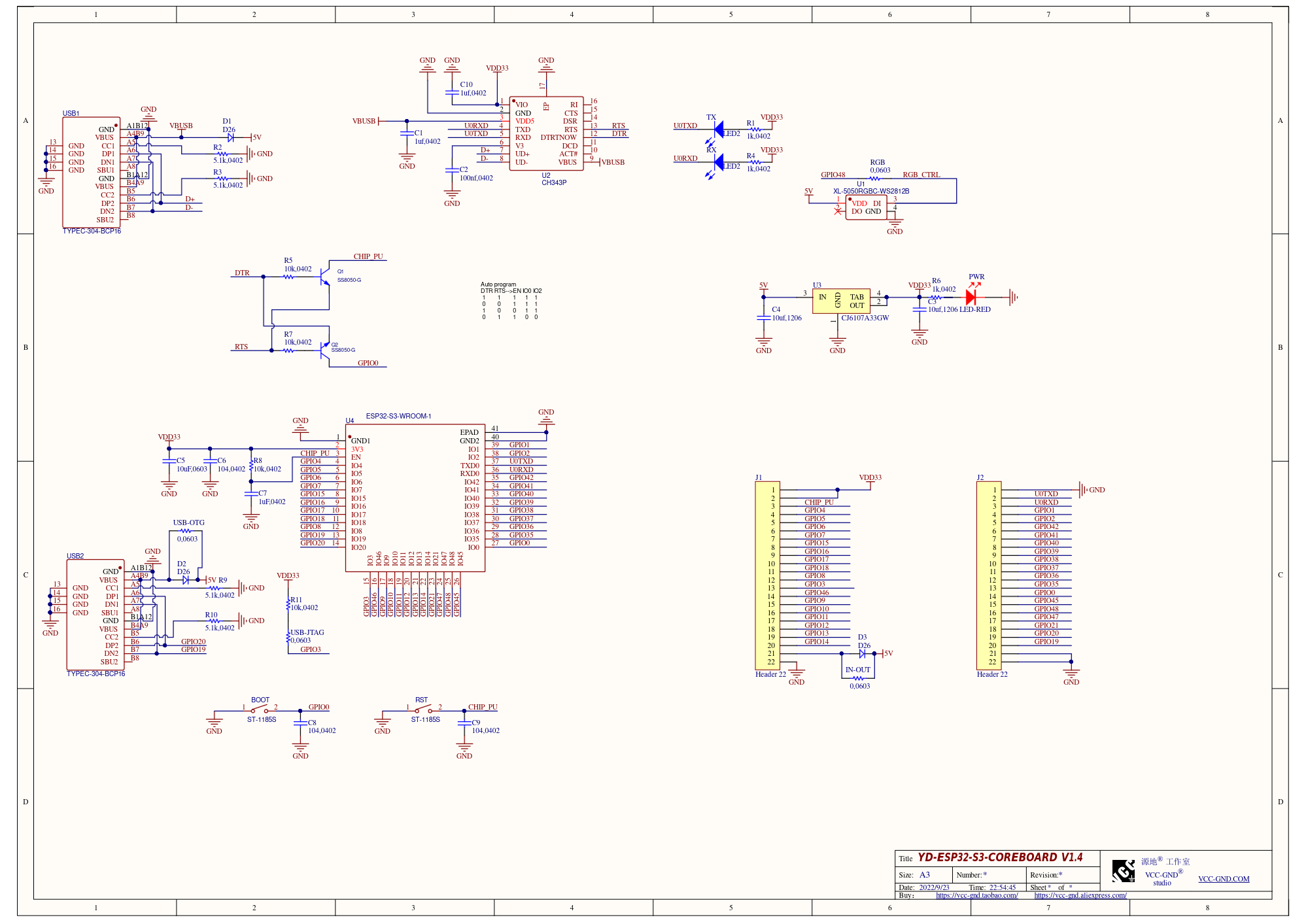
Schematic (Jumpers were not included):