Tutorial
SDR blocks tutorial table of contents
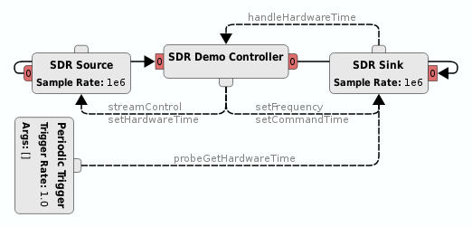
The Pothos SDR toolkit comes with a demonstration control block that shows how to use signals and slots to control the SDR blocks, how to use the receive labels to determine time stamps and ends of bursts, and how to use the transmit labels to control transmit time and bursts.
Please take a look at the DemoController source code. The code is well commented and demonstrates how to use labels, how to use time stamps, and how to make configuration calls.
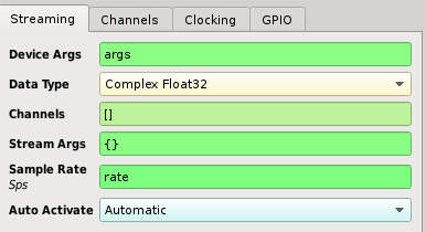
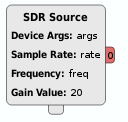
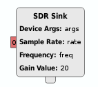
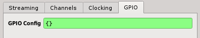
The device arguments are a dictionary of key-value pairs used for specifying a SDR device on the system. If only one SDR device is present on the system, an empty dictionary "{}" may be specified instead.
The key value pairs are the same ones printed by the Soapy SDR Util application:
SoapySDRUtil --find
######################################################
## Soapy SDR -- the SDR abstraction library
######################################################

Found device 0
  backend = libusb
  device = 0x01:0x02
  driver = bladerf
  instance = 0
  serial = 123456789abcdef
- The device argument {"driver":"bladerf"} would cause other drivers, such as rtl, to be ignored.
- Or use {"driver":"bladerf", "serial":"123456789abcdef"} if the system has multiple blade RFs.
The data type is a string that specifies the format of the sample stream. Options are available for all complex, integer, and floating point data types, however not all formats may be supported depending upon the underlying driver for the hardware.
- Note: complex float32 and complex int16 are almost universally supported by most hardware drivers.
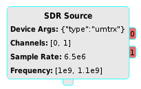
Channels is an array of channel indexes that will be used for streaming. By default this array is empty, meaning that channel 0 of the device will be used. However when specified, each entry in the array maps a device channel to a streaming port.
Stream arguments are a dictionary of key-value pairs used for passing extra arguments to the stream initialization. Implementation of the stream arguments is specific to the hardware driver, however common uses include specifying the underlying transport sample format and internal scaling. Check your device's manual about stream arguments for more information.
This is the sample rate (in samples per second) for all configured stream ports. All channels listed in the channels parameter will be configured to the same sample rate. Otherwise, use multiple blocks to support heterogeneous sample rates for different channels.
By default, the SDR block is activated upon topology activation. This setting can be disabled for advanced stream control, more on this topic in the sections below.
The receive stream may be decorated with several different labels to indicate configuration and events:
- The "rxTime" label is produced at the start of streaming to indicate the stream time. The data of the label is a 64-bit integer containing the device time in nanoseconds. When using the burst capabilities, each burst will start with an "rxTime" label. In addition, "rxTime" is produced after overflow conditions so that downstream blocks can resynchronize their time-tracking.
- The "rxEnd" label is produced at the end of a burst and when streaming has stopped.
- The "rxFreq" label is produced after the center frequency has been configured. The data of the label is a double value representing the frequency in Hz. Many of the signal analysis plotters use this label to automatically configure the axis.
- The "rxRate" label is produced after the sample rate has been configured. The data of the label is a double value representing the sample rate in samples per second. Many of the signal analysis plotters use this label to automatically configure the axis.
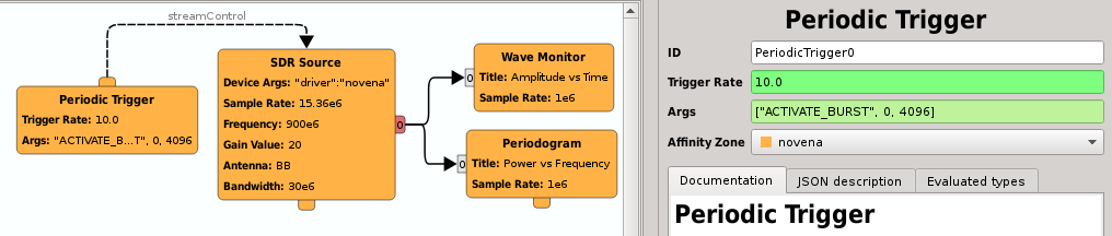
The user has explicit control for bursts and timing using the streamControl() slot. The default behavior of the SDR source is to stream continuously upon activation of the topology. Disable the auto-activation parameter before using advanced the stream control capabilities.

The following arguments can be passed to the streamControl() slot to control streaming:
- streamControl("ACTIVATE") - stream continuously immediately
- streamControl("ACTIVATE_AT", timeNs) - stream continuously starting at timeNs
- streamControl("ACTIVATE_BURST", 0, numElems) - stream a burst of size numElems immediately
- streamControl("ACTIVATE_BURST_AT", timeNs, numElems) - stream a burst of size numElems at timeNs
- streamControl("DEACTIVATE") - halt a continuous stream
- streamControl("DEACTIVATE_AT", timeNs) - halt a continuous stream at timeNs
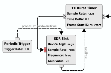
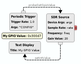
As a useful demonstration of streamControl(), the periodic trigger block can be used to request bursts at a regular rate. Since many of the plotters only display periodic chunks of the sample stream, this little trick makes it possible to visualize a stream from remote or embedded devices that are configured at very high sample rates.
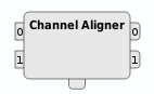
The pothos-sdr toolkit comes with a multi-channel alignment block that uses the hardware timestamps to align the output channels. Use this block in conjunction with multiple SDR source blocks to maintain channel alignment, even in the face of drops and overflows.
Transmit bursts are controlled by stream labels created by upstream blocks. In particular:
- The "txTime" label indicates the transmit time of the first sample in a burst. The data of the label is a 64-bit integer containing the device time in nanoseconds.
- The "txEnd" label indicates the end of a burst to the hardware. Without the end of burst, the hardware may incur an underflow event.
Typically, bursts are sent to the hardware in several fragments. Which means that the hardware can transmit the first fragment before the next arrives. However, burst scheduling can prevent transmission until all fragments arrive.
As a general utility to users and to demonstrate burst-scheduling, the pothos-sdr toolkit comes with a TX burst timer block -- which keeps track of current hardware time and inserts a txTime label into the stream to schedule the bursts.
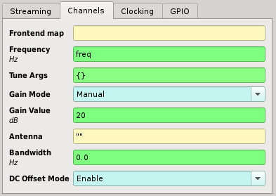
The channel parameters configure elements of the upconversion or downconversion path, such as tuning, filtering, gain control, and antenna selection.
Note0: Most parameters accept either a single value or a list of values to support per-channel configurations. When using a single value, that value is applied to the setting for all configured channels. Its important to note that each index in such a list is associated with a particular port on the SDR block. The Channels parameter from the stream configuration controls the mapping of these indexes to physical device channels.
Note1: Most parameters have an associated slot so that they can be set through the topology with a upstream signal. A parameter will have the slot setFoo() to apply the Foo setting across all channels, and it will have the slots setFooX(), where X is an index, to apply Foo to a specific channel.
The frontend map is a hardware-specific string that maps channels to RF frontends. Most hardware doesn't support this option and frontend map should be left empty. If you device has multiple RF frontends or configurable frontend muxing, you may want to check your device's manual for frontend mapping options.
The frequency specifies the center frequency of the channel in Hz.
- To specify the frequency on a per-channel basis, simply specify a list of values instead of a single frequency. Example: [1e9, 1.003e9] will set port 0's channel to 1e9 and port 1's channel to 1.003e9.
Slots:
- The frequency can also be set through the setFrequency() slot to be controlled by graphical widgets and other upstream blocks.
- Or use the setFrequencyX() slot, where X is a channel number, to set the frequency on a per-channel basis.
The tune arguments are a dictionary of key-value pairs that augment the underlying tuning algorithm. Although the tune arguments are hardware-specific, the following conventions are followed by most drivers:
- Tune the frontend with an offset, compensated by the baseband CORDIC: {"OFFSET" : 1e6}
- Tune any specified element in the chain to a specific frequency: {"BB" : 0.0}
- Ignore any specified element when tuning the chain: {"RF" : "IGNORE"}
- Most devices will use "RF" to specify the frontend synthesizer
- Most devices will use "BB" to specify the baseband CORDIC
Slots:
- The tune arguments can be set through the setFrequency() and setFrequencyX() slots as well by emitting the tune args dictionary as a second optional argument.
The gain mode can be used to enable automatic gain control. Its hardware-specific, and most drivers do not implement it.
The gain value can specify the overall amplification (in dB) for the channel, or can be used to specify amplification on a per-element basis. Examples:
- Specify the overall gain in dB: 15.5
- Specify per-element gain settings: {"PGA" : 10.0, "LNA" : 5.5}
- To specify the gain on a per-channel basis, simply provide a list of gain settings. Each element in the list can be either a single value or a dictionary mapping: [15.5, {"PGA" : 10.0, "LNA" : 5.5}]
Slots:
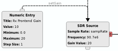
- The setGain() slot can be used to control the gain via graphical widgets and other upstream blocks. The setGain() slot also accepts the single value or gain element map format described above.
- Or use the setGainX() slot, where X is a channel number, to set the gain on a per-channel basis.
The antenna setting is a string that specifies one of the selectable frontend antenna switches. Not all hardware has configurable antenna options, leave the antenna setting empty in this case.
- To specify the antenna on a per-channel basis, provide an array of antenna strings, one string per channel: ["RF1", "RF2"]
Slots:
- The setAntenna() slot can be used to control the antenna switch via graphical widgets and other upstream blocks.
- Or use the setAntennaX() slot, where X is a channel number, to set the antenna on a per-channel basis.
The bandwidth setting configures the baseband filter bandwidth in Hz. Not all hardware supports has a baseband filter or supports the exact bandwidth specified. Check your device's manual for more information, or leave the bandwidth at 0.0 Hz to engage the default behavior.
- To specify the bandwidth on a per-channel basis, provide an array of filter settings, one value per channel: [10e6, 11e6]
Slots:
- The setBandwidth() slot can be used to control the filter bandwidth via graphical widgets and other upstream blocks.
- Or use the setBandwidthX() slot, where X is a channel number, to set the filter bandwidth on a per-channel basis.
The DC offset mode can be used to enable automatic DC offset removal in the hardware. Not all hardware supports this option. Its recommended to either enable this option when available, or to run the calibration utilities for your hardware. DC removal can also be handled in software using a DC removal block.
The clocking parameters are device-wide configurations for clocking and synchronization.
Note0: When using several SDR blocks that represent the same underlying device, its important to apply the same clocking parameters for each associated block to avoid possible undefined behavior.
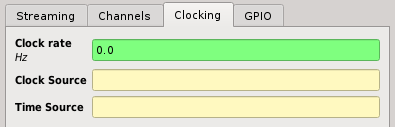
The clock rate is a value in Hz which controls the clock rate of a master synthesizer. Its implementation is hardware-specific and not all rates are possible. The user may need to set the master clock rate to achieve specific sample rates (in the case of integer decimation or interpolation).
If the clock rate configuration is not supported or the default rate is acceptable, users may leave this value at 0.0 Hz -- meaning unspecified clock rate. When the clock rate is specified, its value is applied first, before the sample rate and frequency are set to avoid configuration mishaps.
Specify the a string representing the clock's synchronization source. Many devices have an option to use an external 10 MHz reference, or other such references. See the device's manual for clock source options.
Specify the a string representing the hardware's time source. This synchronizes the hardware timestamps with the specified source. Some implementations may use this to read the time from an internal GPSDO. See the device's manual for time source options.
The GPIO configuration may be used modify one or more GPIO banks or to readback the GPIO state of a bank.
The GPIO parameters uses a special dictionary of key-value pairs to set one or more GPIO banks at activation time. The following keys are supported in the dictionary:
- "bank" - the name of a GPIO bank
- "mask" - an optional modification mask
- "dir" - an optional data direction setting
- "value" - the new value for the GPIO outputs
Note0: The mask parameter is optional and when specified, applies to both the data direction and GPIO value modification.
Note1: The direction parameter is optional and when specified, the implementation sets the direction first before applying a new value.
Set a single bank specified by name:
{"bank":"EXTERNAL", "dir":0x1f, "mask":0x1f, "value":0x05}
Or set multiple banks using a list:
[
    {"bank":"CONFIG", "value":0x72},
    {"bank":"EXTERNAL", "dir":0x1f, "mask":0x1f, "value":0x05}
]
The setGpioConfig() slot can be used to control the GPIOs via graphical widgets and other upstream blocks. Simply use the same configuration dictionary in the configuration widget, or fill a Pothos::ObjectKwargs when producing a configuration signal in C++.
Reading back a GPIO bank can be performed using the GPIO probe signal and slot: Connect a signal to the "probeGetGpioValue" slot to cause query events. The signal should provide an argument for the bank name. Then connect the slot of a display block to the "getGpioValueTriggered" signal to visualize a live display of the GPIO state.
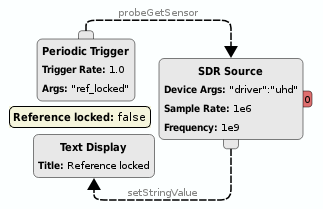
Sensors are arbitrary readbacks for monitoring the state of a device. The available sensors and their names vary from device to device. Most often sensors are used to check for reference lock and to query RSSI (when supported). Just like the GPIO readback, sensors can be queried through the signal and slots probe mechanism.
Global sensors are associated with a component on the device that is common across transmit and receive chains, such as reference lock. To trigger a global sensor read, an upstream block emits a signal with the sensor name as a parameter to the "probeGetSensor" slot. The SDR block will emit the sensor value on the "getSensorTriggered" signal.
Channel sensors are associated with a particular streaming channel, such as lo_locked for the RF frontend. To trigger a channel sensor read, an upstream block emits a signal with the sensor name as a parameter to the "probeGetSensorX" slot, where X represents an available channel index. The SDR block will emit the sensor value on the "getSensorXTriggered" signal.