Blinken lights are everybody's joy, and this is no exception. IKEA has several "DIODER" LED bars or flexible strip.
Of course there are better alternatives: cheaper or with more features or lights. But they are not realily available with power adapter and everything.
Each bar has eight multi-color LEDs. Each LED has in fact three mini-leds, one for each primary color: red, green and blue.
Unlike other circuits that share the ground contact (0V, minus "--", GND), the circuits for the color LEDs share the 12V "+" line (or VCC) and have separate grounds.

Please note that all the images are available on Flickr.
To light a mini-LED, you connect its ground to 0V (or GND) line. So there are four wires needed to light independently each color: one VCC and three GNDs for each color.
So to have a color at 100%, the voltage on the LED gnd should be 0 V. To have it completely turned off (blank), you need to supply VCC (12V), so that no current flows.
- The gear in the Dioder package
- Arduino (I have Arduino UNO)
- Several transistors to handle 12V (Arduino pins work at 5V)
- A bread board (for transistors, resistors etc.)
I don't have the transistors, nor the experience to work with transistors (as of Dec. 2013).
So I took a chance and used Arduino pins without resistors to limit the current and without transistors to make everything by the book. There is a chance that the Arduino internals get burned in the process but for me it didn't happen.
But there is a catch. A bare pin can supply 0V to make light the color fully, but cannot supply 12V to turn off the LED.
However having 5V on the pin can make the LED dark enough to see the difference.
To light 100% a color, I did an analogWrite(pin, 0) on color's minus pin.
To darken a color, I did an analogWrite(pin, 255).
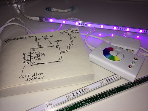
The internals of the DIODER are pretty simple to figure out, at least for the connections.
The power adapter provides VCC to the controller and to the LED bars, and the GND is passed to the controller which in turn gets it back to the LED bars for each color.
There are five pins for the controller connector: VCC, Green, Blue, Red, GND. VCC and GND are inputs for the controller, the rest are outputs for the controller and inputs for the LED bars.
So to control the thing, you need to replace IKEA's controller with the Arduino Circuit.

I used male-female wires. Ikea used the standard pin distance, so they fit perfectly in the controller socket without any modifications.

The code to control the colors is easy. Remember that without transistors or other electronics, you cannot get the full range of colors. But luckily, you're on the bright side :)
#define R 9
#define G 10
#define B 11

void setColor(int red, int green, int blue) {
    analogWrite(R, 255 - red);
    analogWrite(G, (255 - green) / 1.05);
    analogWrite(B, (255 - blue) / 1.2);
}
and in setup():
pinMode(R, OUTPUT);
pinMode(G, OUTPUT);
pinMode(B, OUTPUT);
A working code example is the .ino file in this repository. The example reads an analog sensor input (pin A0) and turn the LED bars redish if the reading is higher than the last 100 readings average or blueish if the reading is less than the average. Works well for temperature or humidity sensors
The final goal is to make the lights color Internet aware, so there is some work to do, still, but anyway, the first proof of concept is ready.
If you can help, I am happy for any advice, code or anything. My Twitter is @cdinu.
You may want to connect directly to the LED bar without the small box, to have the bars display different colors. Here is the socket pinout. You will need to supply 12V (VCC) and each bar will need another three pins and a breadboard.

I am not affiliated and have no link with IKEA. IKEA and pobably DIODER brand are registred trademarks of IKEA.
I was lucky and did not burn any circuit and my house didn't catch fire as a result of this experiment. Don't held me responsible if anything happens to you.
No license. Public domain. Use it however you want.